 CH
CH English

Cycloidal pin wheel reducer
Power range: 0.37KW~55KW
Torque range: 150N · m~20000N · m
Speed ratio range: Single stage: 9-87 Double stage: 121-7569 Third stage: 2057-658503
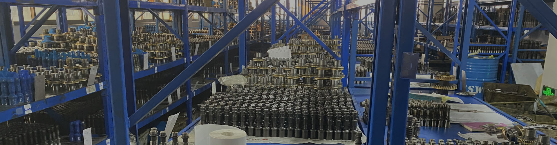
Machinery manufacturing company from China.
Choose Us, Trust Us!
Power range: 0.37KW~55KW
Torque range: 150N · m~20000N · m
Speed ratio range: Single stage: 9-87 Double stage: 121-7569 Third stage: 2057-658503
Cycloidal pin gear reducers use the principle of cycloidal pin tooth engagement and planetary transmission, so they are commonly referred to as planetary cycloidal gear reducers. Planetary cycloidal pin gear reducers can be widely used in industries such as petroleum, environmental protection, chemical engineering, cement, transportation, textile, pharmaceutical, food, printing, lifting, mining, metallurgy, construction, power generation, and other industries. As drive or reduction devices, the machine is divided into horizontal, vertical, dual shaft, and direct coupling assembly methods. Its unique stable structure can replace ordinary cylindrical gear reducers and worm gear reducers in many cases. Therefore, planetary cycloidal needle gear reducers are widely used in various industries and fields, and are widely welcomed by users.
Service conditions
1. The cycloidal pin wheel reducer is allowed to be used in continuous duty situations, while allowing both forward and reverse directions of operation. Some models of cycloidal pin wheel reducers only allow single direction rotation.
2. The rated rotational speed of the input shaft is 1500 rpm. When the input power is greater than 18.5 kW, it is recommended to use a 6-pole motor of 960 rpm for matching.
3. The working positions of horizontal mounted cycloidal pin wheel reducers are all horizontal. The maximum horizontal inclination angle during installation is generally less than 15 °. Other measures should be taken to ensure adequate lubrication and prevent oil leakage when the temperature exceeds 15 °.
4. The output shaft of a cycloidal pin gear reducer cannot withstand large axial and radial forces, and other measures must be taken when there are large axial and radial forces.
Lubrication
1. Under normal conditions, horizontal cycloidal gear reducers use oil pool lubrication, and the oil level can be maintained at the middle of the oil viewing window. When working conditions are harsh and the ambient temperature is high, circulating lubrication can be used.
2. Cycloidal needle gear reducers are generally lubricated with 40 # or 50 # mechanical oil at room temperature. In order to improve the performance of the reducer and extend the service life of the cycloidal needle gear reducer, it is recommended to use 70 # or 90 # extreme pressure gear oil. When operating at high and low temperatures, lubricating oil may also be reconsidered.
3. For vertically mounted planetary cycloidal pin wheel reducers, it is necessary to strictly prevent the oil pump from cutting off oil to avoid damage to the components of the reducer.
4. When refueling, you can unscrew the vent cap on the upper part of the seat to refuel. When draining oil, unscrew the oil drain plug at the bottom of the engine seat to drain the dirty oil. There is no lubricating oil inside the reducer when it leaves the factory.
5. After the first 100 hours of refueling operation, the oil should be replaced with a new one (and the internal dirty oil should be washed clean). After that, continuous operation should be carried out, and the oil should be replaced every six months (8-hour working system). If the working conditions are poor, the oil change time can be appropriately shortened. Practice has proven that frequent cleaning and oil change of the gear unit (such as 3-6 months) have an important role in extending the service life of the gear unit. The lubricating oil should be frequently replenished during use.
6. The factory reducer has been greased and replaced every six months. The grease is aluminum disulfide - 2 # or 2L-2 # lithium based lubricating grease.
Install
1. When installing couplings, pulleys, sprockets, and other connecting pieces on the output shaft of a cycloidal gear reducer, it is not allowed to use the direct hammering method. Because the output shaft structure of the gear reducer cannot withstand the axial hammering force, it is possible to screw in the screw hole at the shaft end to press in the connecting piece.
2. The shaft diameters of the output shaft and the input shaft shall be in accordance with GB1568-79.
3. The eyebolt on the reducer is only used for lifting the reducer.
4. When installing the reducer on the foundation, the installation center line elevation, levelness, and related dimensions of the connected parts of the reducer should be calibrated. The concentricity of the calibration mounting shaft should not exceed the allowable range of the coupling.
5. When calibrating the speed reducer, steel or cast iron pads can be used. The height of the pads should not exceed three, and wedge iron can also be used. However, after calibrating the speed reducer, a flat pad should be replaced.
6. The arrangement of cushion blocks should avoid causing deformation of the body. They should be arranged symmetrically on both sides of the foundation bolts, and their mutual distance should be sufficient to allow the water slurry to flow freely during irrigation.
7. The irrigation of cement slurry should be dense and free of bubbles, voids, and other defects.